×
×
Before attempting to adjust the red light offset, ensure that the scale tube and copper nozzle are securely installed and not loose.
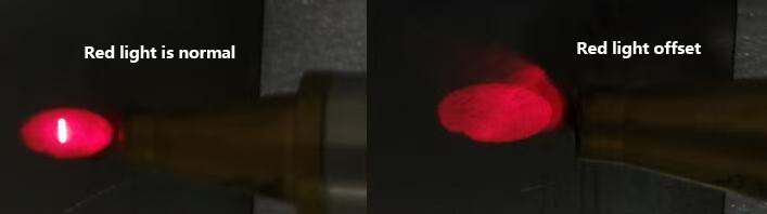
Graph 1. Comparison of red light states.
1. Adjustment methods(1) - Software Settings (Left/Right Adjustment)
Fine-tuning is done through the laser center offset setting in the settings interface.
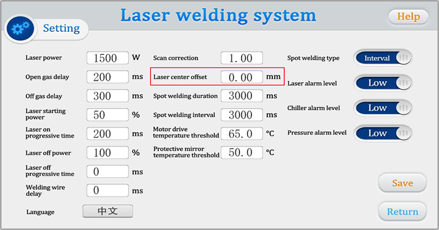
Graph 2. Laser offset parameters.
As shown in Graph 2, changing the laser center offset value moves negative values to the right and positive values to the left. The latest version allows for a maximum adjustment of ±3.
This method allows for left/right fine-tuning. If this method still fails to achieve the desired adjustment, mechanical adjustment is required.
2. Adjustment methods(2) - Mechanical Adjustment (Up/Down/Left/Right Adjustment)
Before performing mechanical adjustment, please ensure that the center offset setting is set to “0”.
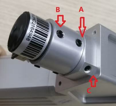
Graph 3. Motor structure.
Significant left/right deviation: Loosen C, rotate the locking ring, being careful with the rotation range; apply only slight force (do not rotate the motor part, i.e., the area with the SN code label).
Upward adjustment: ① Loosen the screw below B and tighten screw B; ② Loosen screw A and tighten the screw below A.
Downward adjustment: ① Loosen the screw below A and tighten screw A; ② Loosen screw B and tighten the screw below B.
 Hot News
2025-11-01
2025-12-03
2025-12-01
2025-11-25